Soemtron ETR224
Skip to navigation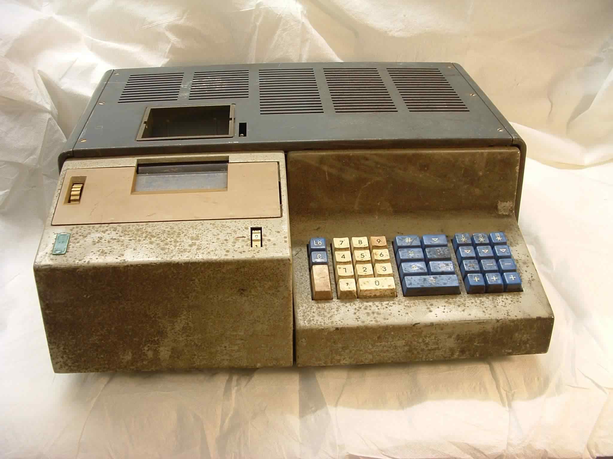
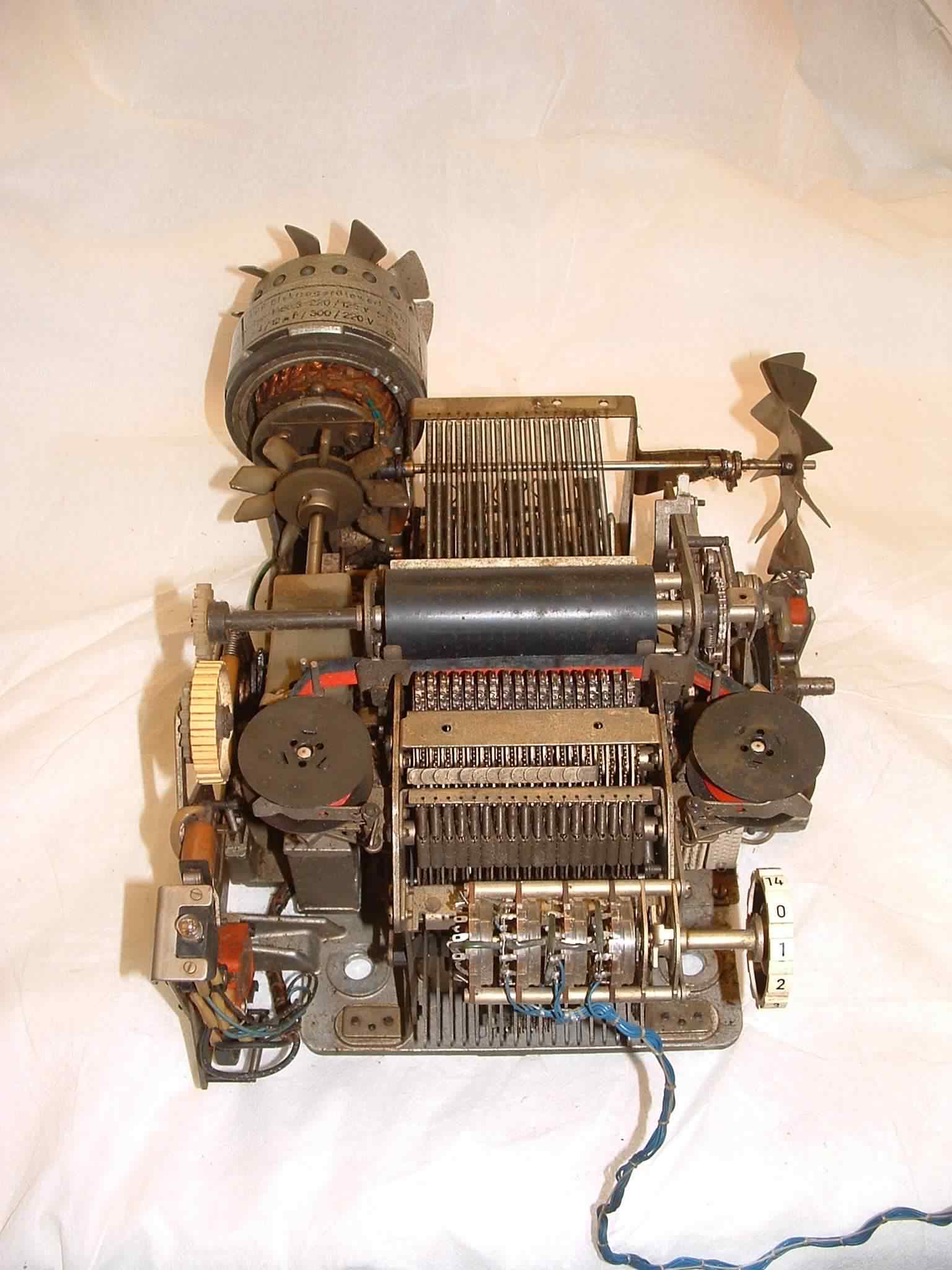
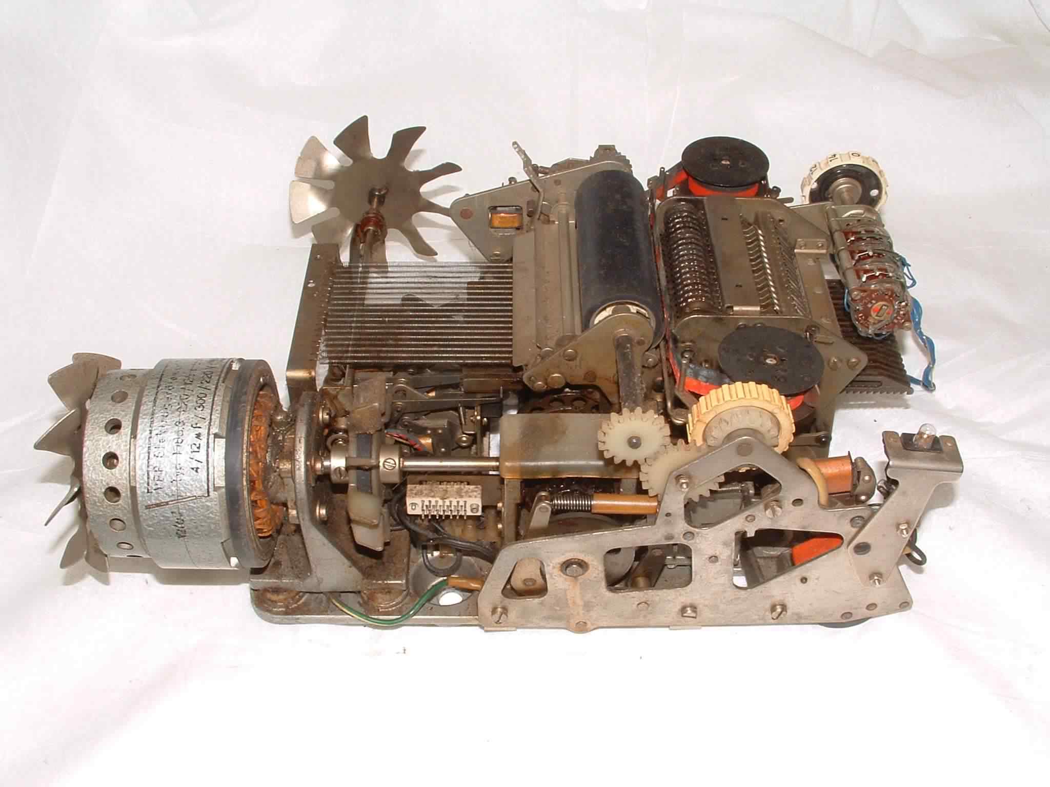
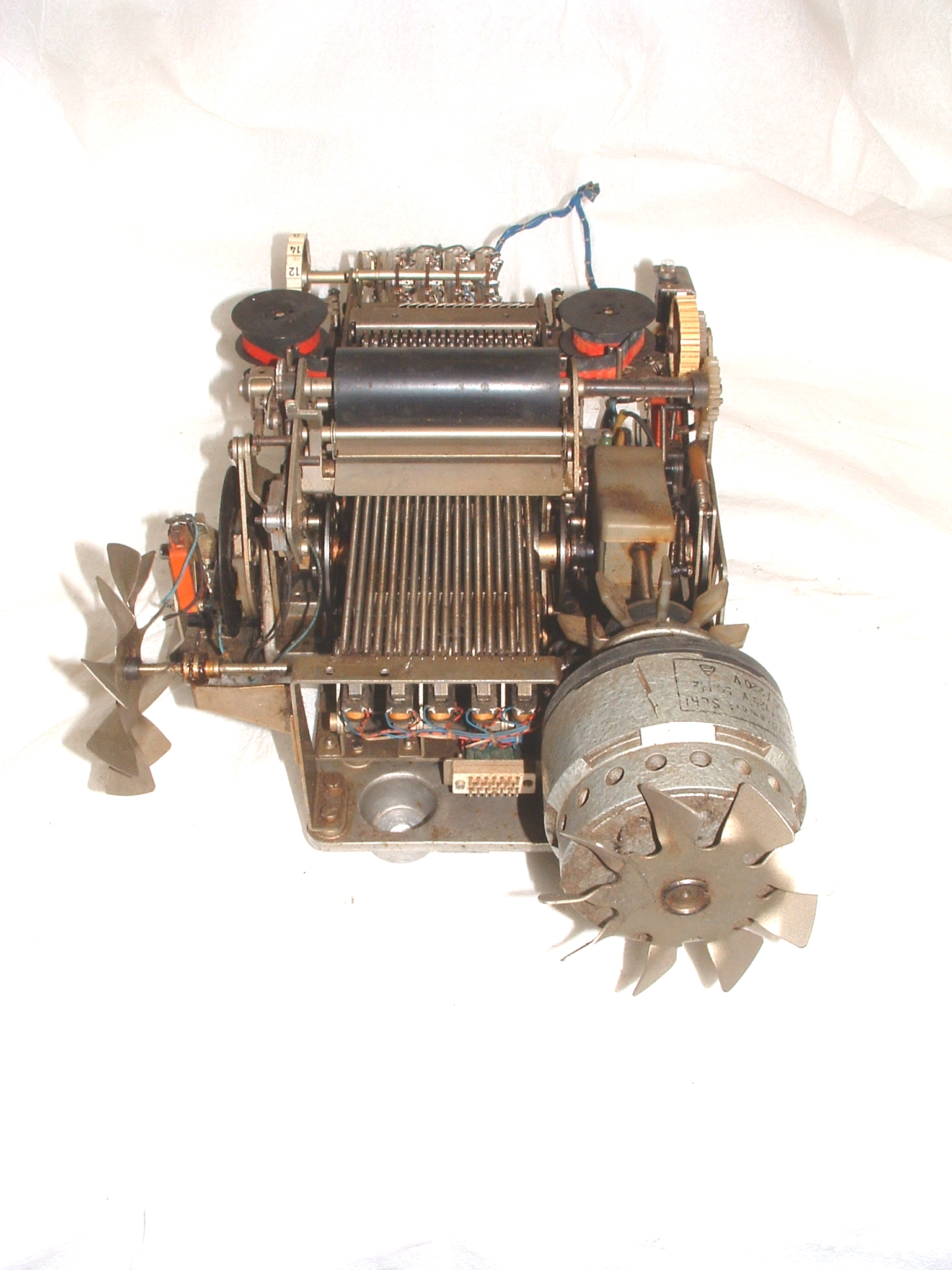
Our ETR224 in its original dirty state
Click image for a larger version
S#32612 - Restoration & technical description
All images ©www.soemtron.org 2007–
Our ETR224 is serial numbered 32612, which seems to roughly agree with the 1969 date codes on most of the boards, however the Core memory and Driver boards are dated 1972, so we presume they were replaced at some point in the machines history. These two boards are ETR220 part coded and are the only boards that appear to be common over the whole Soemtron ETR22x range. Our machine was very, very dirty (it apparently was used in a meat processing factory!), and would also seem to have been stored on its back for many years judging by the way all the vertical surfaces on and inside the machine are dirtiest, we also think that when it was in use it was on top of some other piece of equipment which has forced dirty air up and into the ETR224 through the base ventilation slots.
Internally the condition is quite good and does not show signs of the patchy external corrosion. The machine closely resembles the Museum's ETR224, but has an extra mechanical drive through the printer mechanism to an additional fan housing on the card cage. The right angle friction drive from the motor coupling for the fan is not functioning properly, probably due to misalignment in the fan shaft assembly along with a degraded rubber "O" ring. What looks to be the drive electronics for the printer solenoids is behind the printer, whereas in the Museum's ETR224 those boards are mounted on the side of the card cage, that location in our machine has the fan housing.
This Soemtron ETR224 has also been dropped at some time in the past as the main card cage is bent and one of the reservoir capacitors has some very bad scrapes (picture #29) from the motor fan. On close inspection these appear to have actually punctured the capacitor case although no leakage is evident. Connections to the digit detector photocell on the printer mechanism are also broken, presumably from continued flexing of the wiring. Some of the electronics boards show that extensive repairs have been carried out in the past, backed up by visible damage to the top edge of the main card cage. All of the case parts have been re–sprayed as they were too heavily corroded to recover.
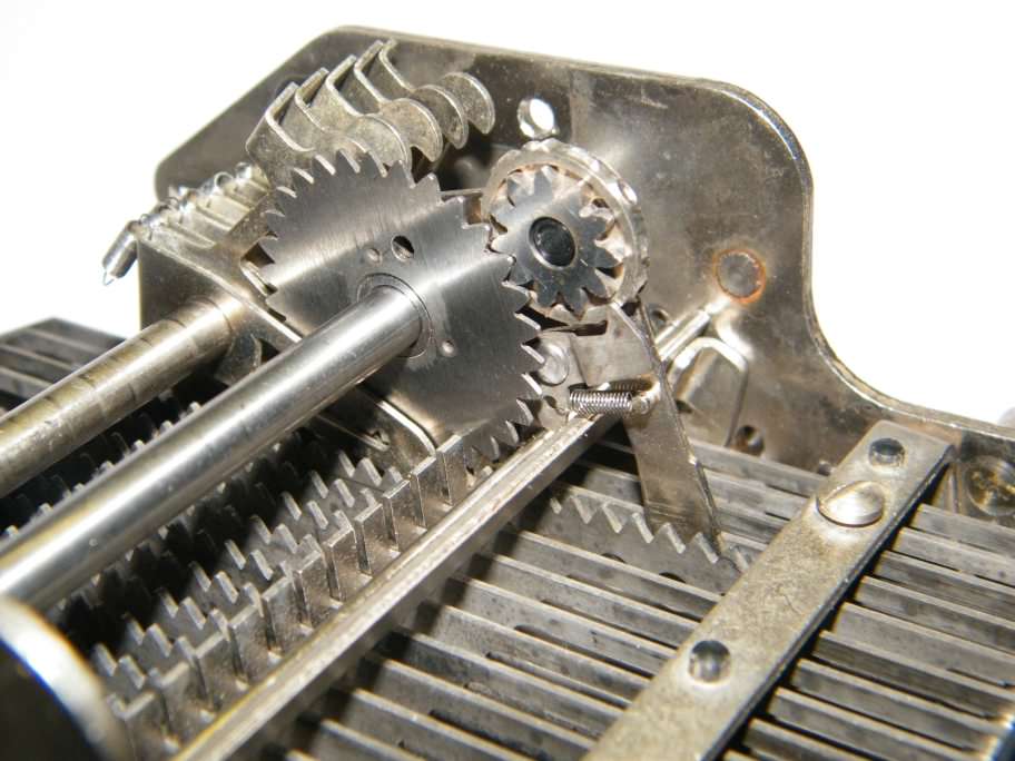
Print wheel layshaft assembly
Click image for a larger version
The printer mechanism is now clean and reassembled, but we found that one of the print wheel arms was bent and would not contact its idler gear or the print platen correctly. This bent arm has been realigned and testing continues. Having got most of the mechanism back together and run the motor it was evident that the transverse fan assembly bearings at the fan end are loosely toleranced or badly worn and have a large amount of "bearing slap" resulting in a lot of noise reverberating through the blades. These worn bearings have been replaced and a new rubber O ring fitted to the friction drive, the fan is now working well and is very much quieter.
During disassembly of the printer mechanism it was found that the cam actuated bar used to return the 18 selector racks, was broken in two, so the some of the print wheels would potentially not return to their correct rest positions. The broken part was temporarily welded back together for testing purposes but the part has now been accurately measured and drawn, and two new bars (one a spare) have been manufactured so that we can effect a full repair in the future. During preliminary testing of the re–assembled unit we have also noticed a large amount of rotational miss-alignment of the print wheels whilst at their rest position through the idler gears back to the selection racks. This appears to be related to another cam actuated bar that simultaneously releases all eighteen print wheels to make the print impression through the ribbon. As it appears there is no adjustment for this (the bar is pinned and screwed in position), we may need to look for other possible problems with the mechanism, and then re–pin the bar or have a new part made and re–pin that.
Complete circuit - circuit (drawing subject to unannounced changes)
All the current issue drawings in one file.
See the 224 snagging list for the current list of circuit diagram problems to sort out for our ETR224.
Backplane - circuit
A preliminary circuit diagram for the ETR224 backplane is available from the links above. The backplane in our machine is labelled 224-307-013c which we presume gives it an issue level of "c" for board "13" which is usually the backplane in the Soemtron calculators. The backplane and card chassis is very similar to the Soemtron ETR220 later version (board 1 left - board 12 right) machines, but in the ETR224 it is located with board 1 (memory core) to the rear by the power supply. Boards 1 & 2, the core memory and drivers, are standard ETR220 boards. What would have been the display drivers on boards 11 & 12, are now assigned to other logic functions, as the ETR224 does not have the 15 digit Nixie display, any remaining keyboard encoding circuits have been moved to the keyboard itself (see below) as is also the case with the ETR222.
Keyboard - circuit
Duplicating the keyboard layout of the ETR222, the keyboard for the ETR224 is placed to the front right of the machine with a boxy die-cast cover for the printer mechanism at its left. It is not known why this rather bulky layout was adopted rather than the more useable layout as seen in the ETR221 pictures, but it could be related to possible operational problems with the 221 due to the long umbilical cable between the printer - keyboard unit and the electronics module. The Soemtron ETR224 layout as it is, only readily lends itself to right handed operation, left hander's may find it very awkward to use. With the same keyboard layout as that found in the Soemtron 222, the Soemtron ETR224 keyboard also has the same differences to the original Soemtron ETR220 layout, which are -- The sign or negate entry key (220 -#) is moved from the central functional key group to the space below the Clear key C previously occupied on the ETR220 by the decimal point key , - which then
- moves to a new location under the numeric 1 key left of the now slightly smaller zero 0 key. The current decimal point position (overlaid 0 and 1 digits to show as a "barred" 0), is now not visible in the display during numeric input.
- The ETR220 "Raise to Power" function key Xn has been removed. For powers on a ETR224 the base number X is first keyed in, then for the exponent n, the multiplication key is pressed n-1 times, then the equals key once. This key position has become the "return constant" ∇ key.
- Lastly the key position on an ETR220 for the "sign or negate entry key" -# becomes the "Exchange operands" # key which swaps the contents of both operand registers.
| Lö | 7 | 8 | 9 | # | ∇ | I ✶ | II ✶ | III ✶ | |||
| C | 4 | 5 | 6 | x | : | ∇ | ∇ | ∇ | |||
| - | 1 | 2 | 3 | + | - | - | - | - | |||
| , | 0 | = | + | + | + | ||||||
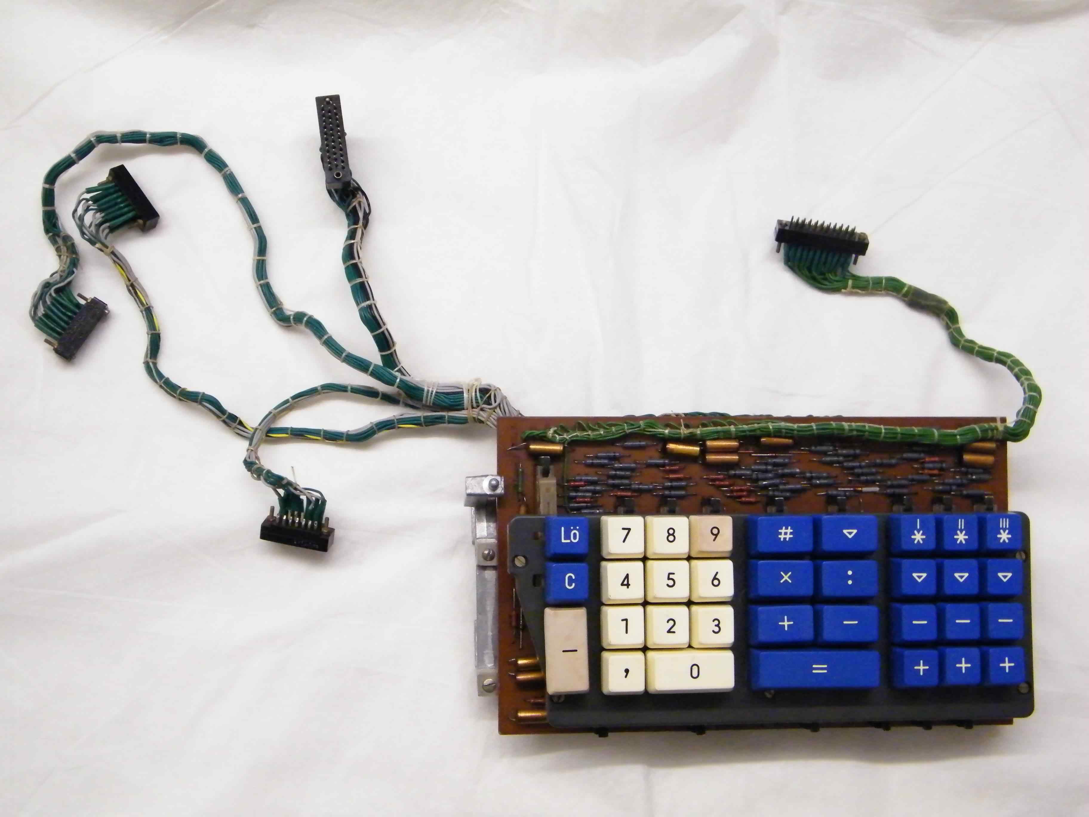
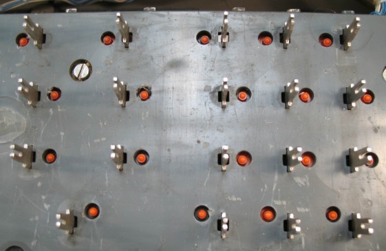
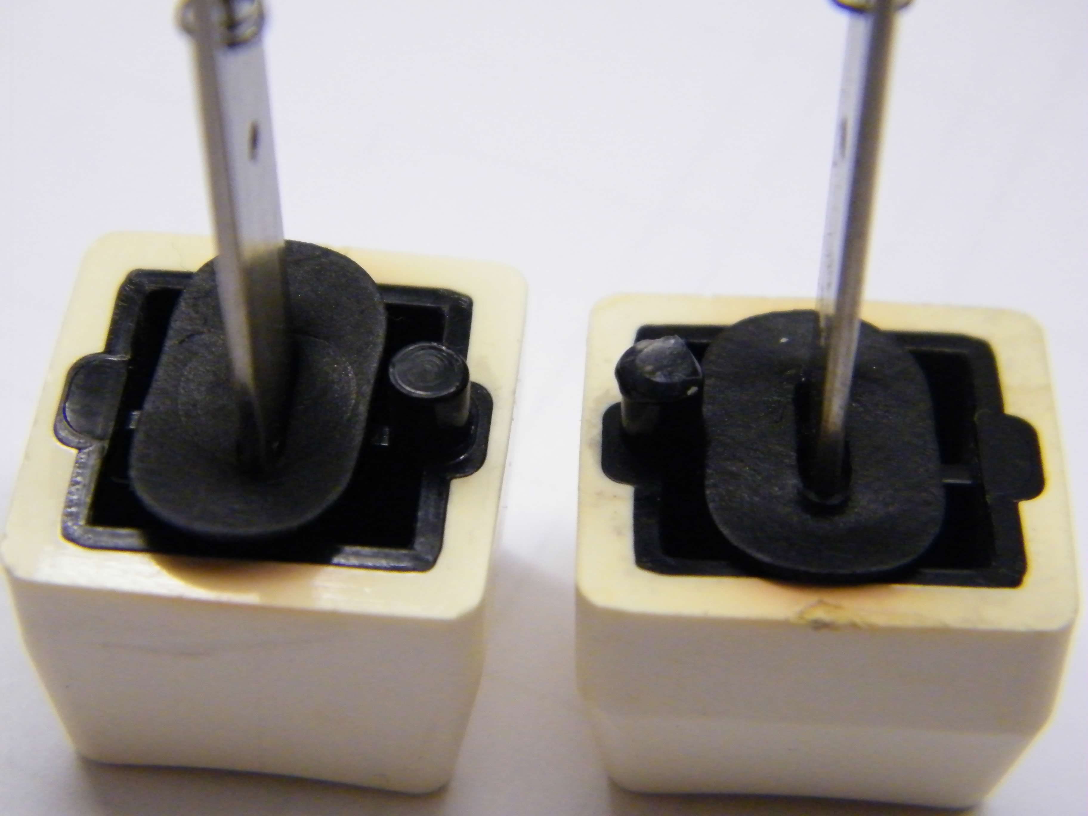
The ETR224 keyboard consists of 32, microswitches with Blue keys for control and functions, and White keys for numeric entry (see photo above), arranged in 4 logical groups broadly similar to the ETR220 thus -
- Clear and sign keys - Clear Lö , Clear entry C and negate entry -
- Numeric keys - 0-9 , arranged in the normal order as seen on modern computers and calculators, and decimal point ,
- Arithmetic functions - exchange operands # , return constant ∇ , Multiply X , Divide : , Add + , Subtract - and Result =
- Register controls - for registers I , II , III - Recall with clear ✶ , Recall ∇ , Subtract - and Add +
Top
Underneath
Click an image for a larger version
In refurbishing our ETR224 we stripped out the keyboard assembly and disassembled it to its component parts which were then washed in warm soapy water, the keys were particularly filthy as can be seen from the photo of the original machine above, needing cleaning with a cream cleaner to get the many years of accumulated grease off, surprisingly they now look very good except for a couple of faded and crazed key tops. The keyboard circuit was also thoroughly washed to get the dust and grease off and all the parts were left on top of our boiler for a few days to thoroughly dry out. The keyboard circuit was then reverse engineered to get the circuit diagram and then tested for functionality, where we found a few of the encoder diodes were faulty. Initially we found a few of the switch contacts were also playing up and that there were also couple of bad solder joints. Having electrically cleaned the switch contacts and reflowed the solder joints we used a small custom display circuit to show the encoded output states of the rebuilt keyboard assembly. Several signals were not behaving as expected with signals KY(+1), FUNCTKY and KBD(-1), KBD(CLR) and NUMKEYS appearing shorted.
Leaky diodes turned out to be the problem, as has been suggested by several contributors to this website in the past. The faulty diodes were all the Grey painted (Febana[1]) OA741 Germanium type, which after replacement with the ubiquitous 1N4148 Silicon device the encoding problems of this keyboard were cured. Later testing of the faulty diodes with various meters (electronic and analogue) appeared to indicate that they were good but testing for reverse leakage currents at 12V showed them to have values ranging between 5µA and 30µA, confirming them to be faulty. Being Germanium diodes it was also possible to see a marked increase in leakage current with temperature, just holding the faulty device between your fingers resulted in a 20% increase in the leakage current.
Images (above) ©2011 Serge Devidts
Click any image for a larger version
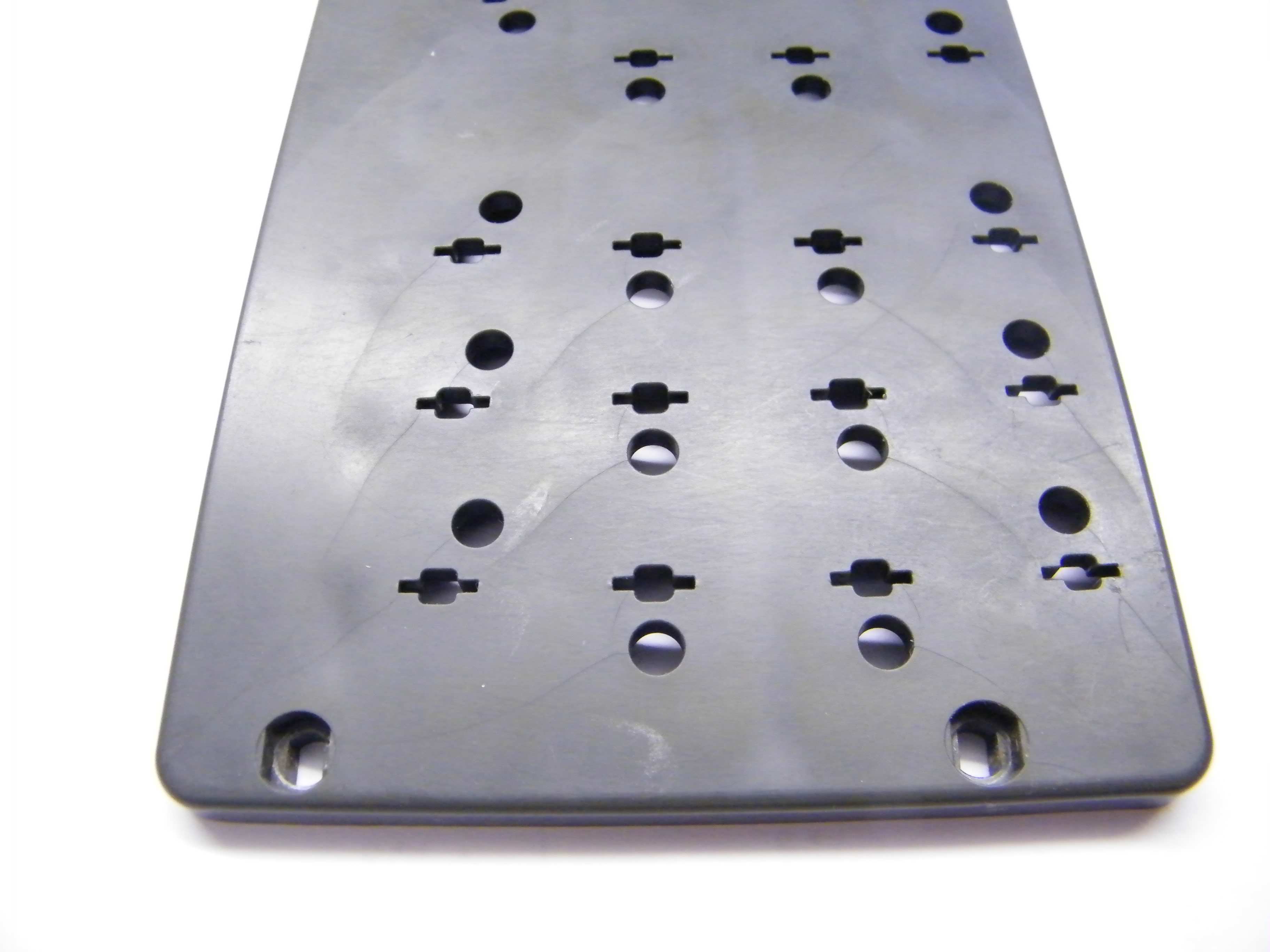
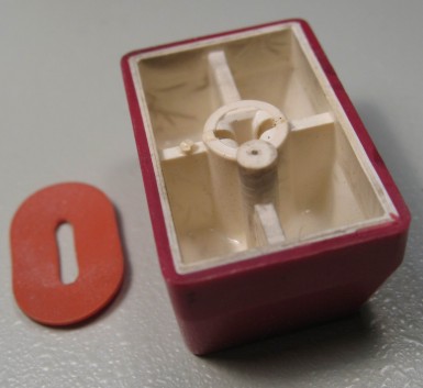
Crazed plastic carrier Modified key caps
Mechanical reassembly of the keyboard gave rise to a few unforeseen problems not encountered with our other Soemtron keyboards. The Grey plastic mechanism carrier of this ETR224 has some aging problems and is riddled with very small uniform directional cracks (see lower left photo), probably resulting from stresses in the original injection moulding process. The panel is still serviceable and seems to be quite strong but is slightly non–planar especially in the area of the 4 5 6 and 7 8 9 numeric keys, the 7/8 keys were not working at all as the keys bottomed out on the panel before the switch activated, other keys required some pressure to activate. Adjusting the microswitch positions is not very practical as it necessitates re–soldering a switch on a single sided PCB, however a couple of keys did respond to this rework process but not enough to make much of a difference. What did eventually cure all the non–operational keys was the judicious application of a small amount of hot melt glue to each keycap's switch pin, which was left to harden and then trimmed, effectively lengthening the pin (see lower right photo). This ETR224 keyboard is now fully functional, one less problem on the journey to getting this rare machine back into life.
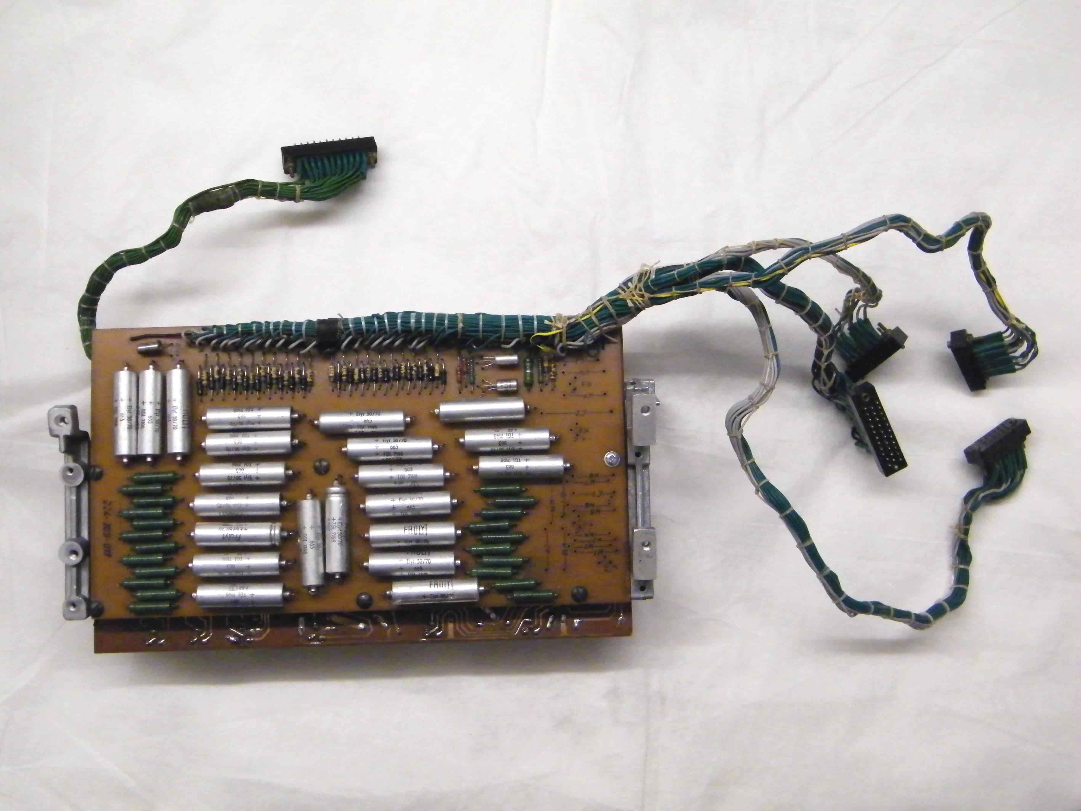
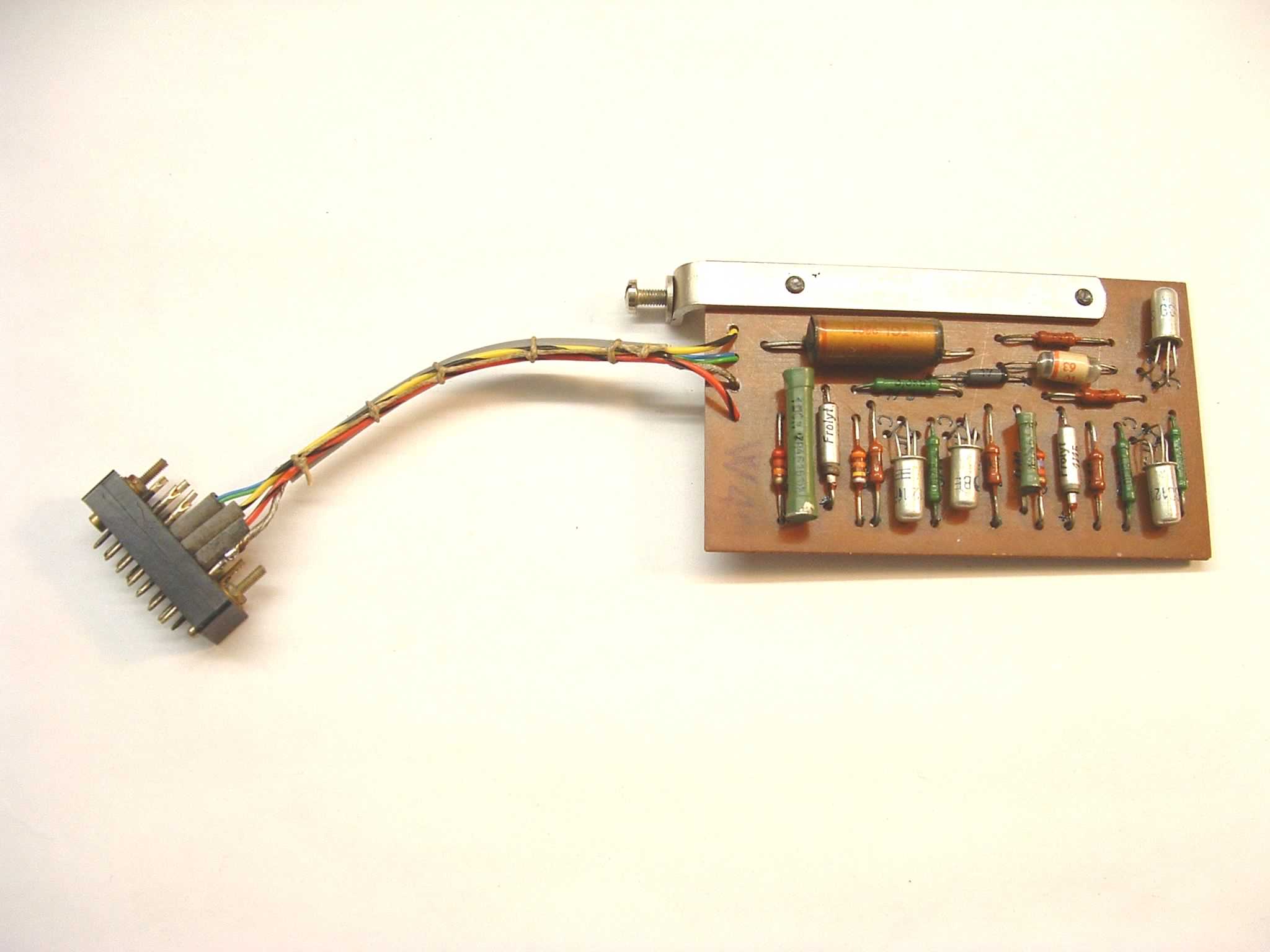
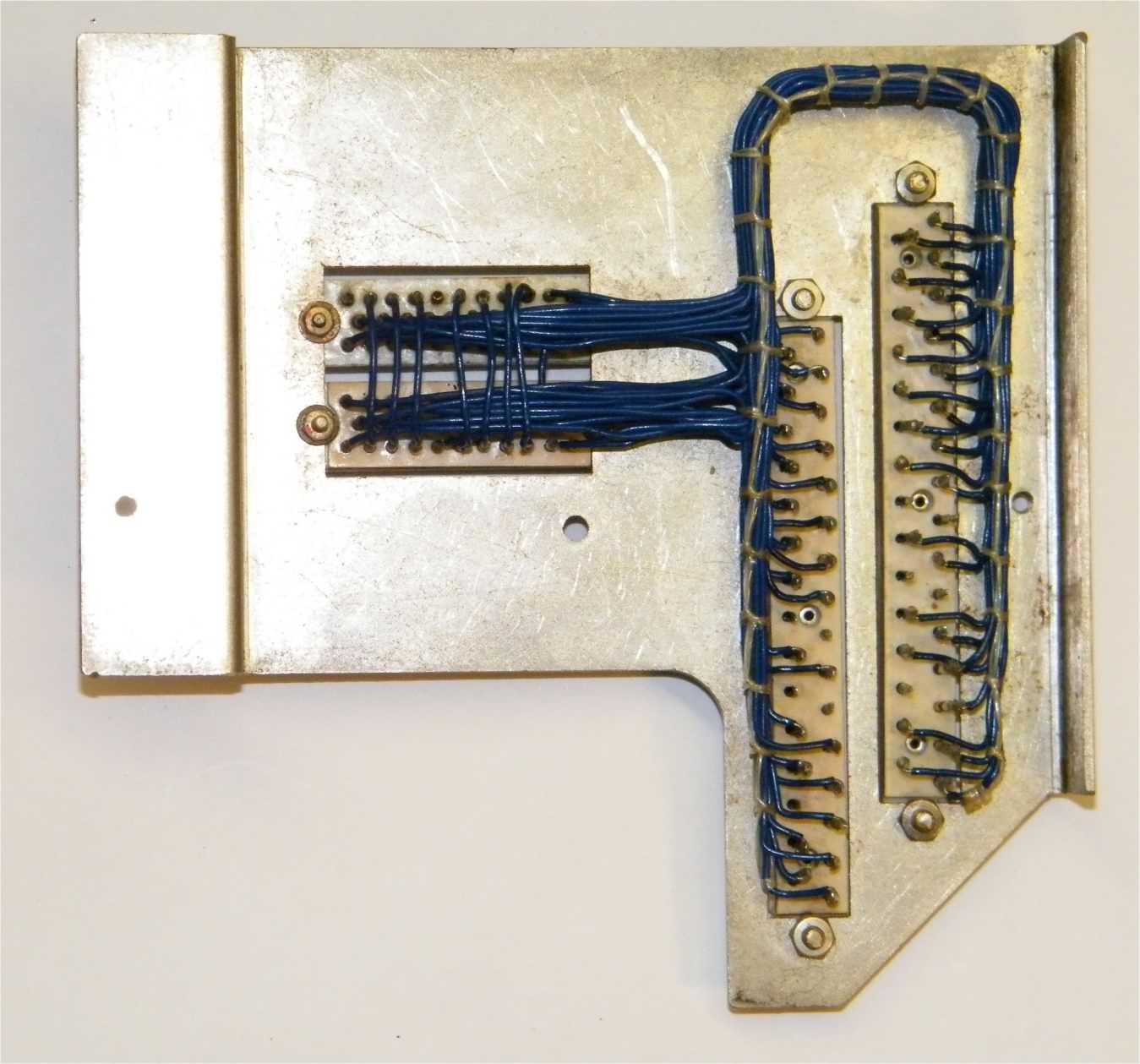
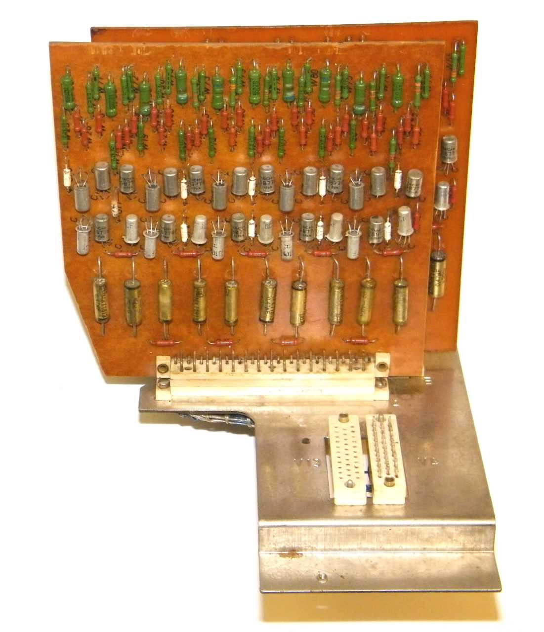
Under keyboard wiring - circuit
Located under the keyboard is a board with an unknown function, although it appears to be a set of driver - monostables. With 20 identical circuits which are connected to the printer solenoids, it appears to be a form of pulse generation and driver circuit. This aggregated circuit for the "double space" solenoid, which advances the paper platten by two lines, shows the DBL driver from driver board B with associated bits of the wiring loom and the diode/resistor matrix from the under keyboard PCB. The circuit appears to be a monostable (TR16 / TR22) with power driver (TR2) and protection diodes (GR6/7). This board also contains a unpopulated circuit area identical to that now located on the small digit position photo–sensor amplifier board in front of the printer. It can only be surmised that the original location of the amplifier under the keyboard gave rise to serious signal noise problems from the pulse circuits requiring its moving to a newer isolated position.
Power supply - circuit
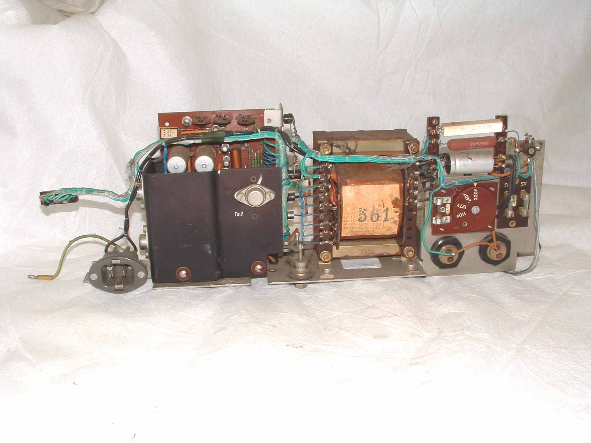
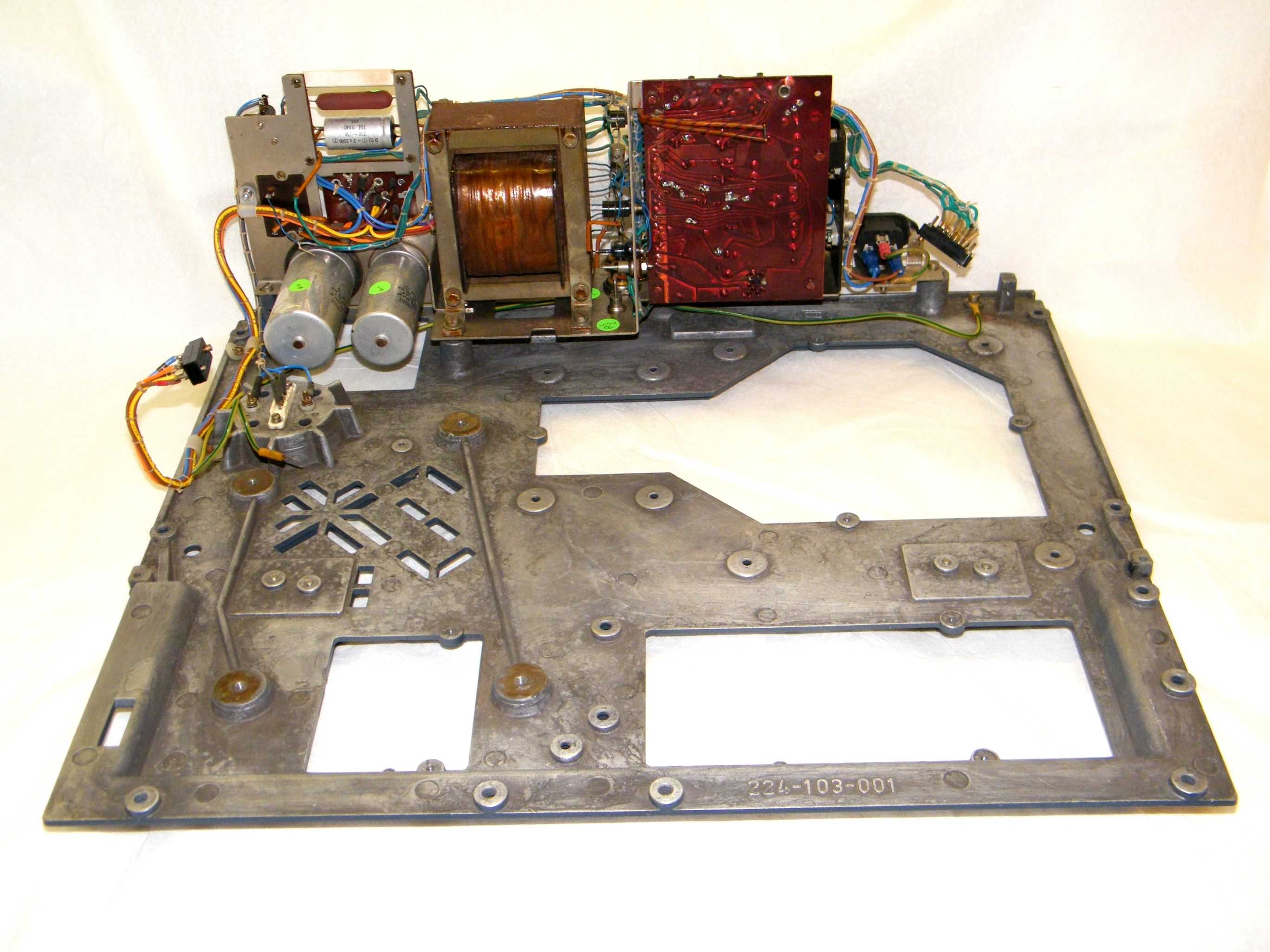
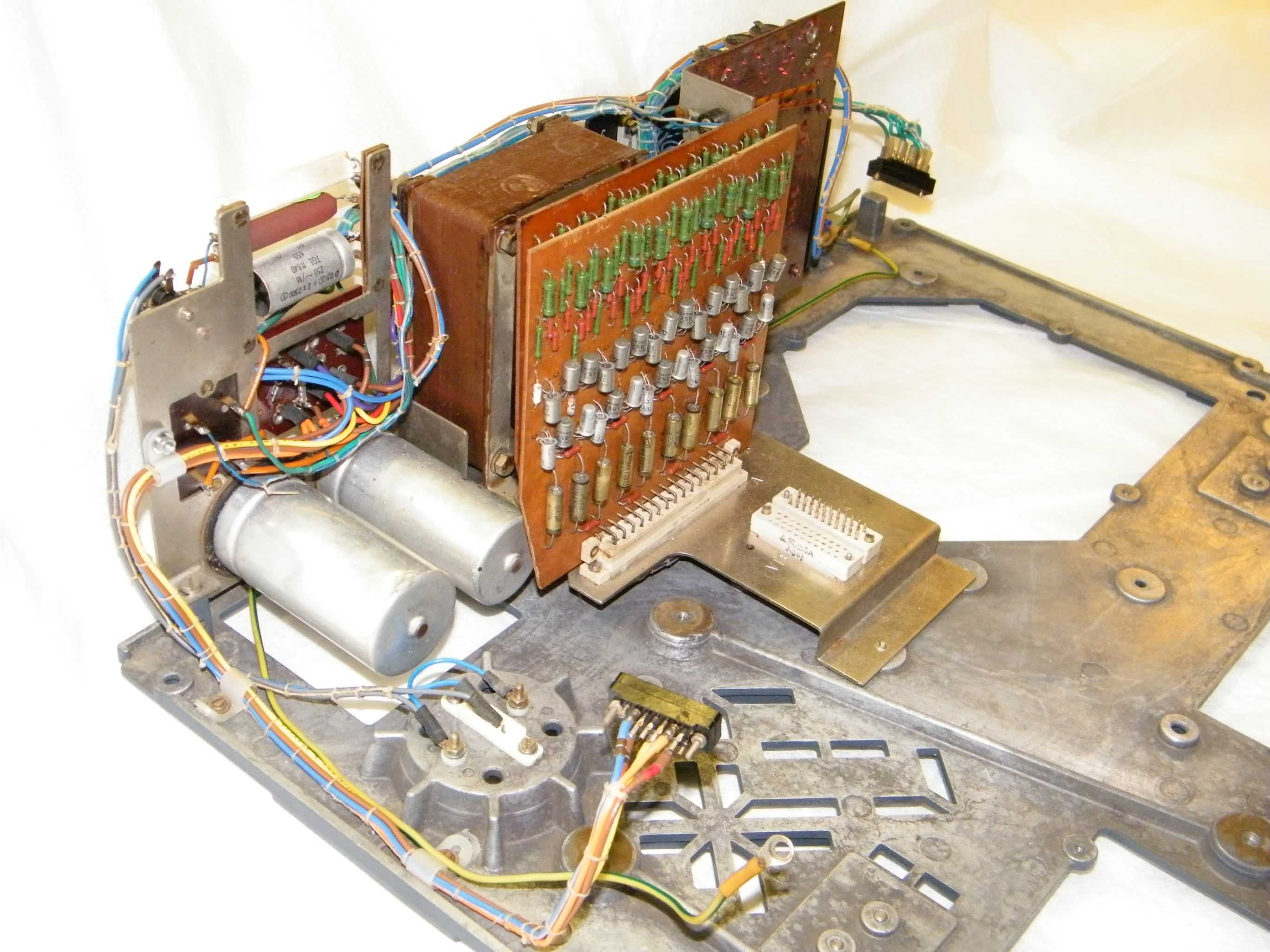
The main ETR224 power supply unit uses the same basic PCB assembly as the ETR220 and 222 machines, but is configured to give five DC outputs of -11V (-Ua[d]), -12V (-Un), -13.5V (-Usp), -30V (-Ua) and +12V (+Up). Mechanically it is constructed as a long thin block rather than the cube shape of the ETR220 and 222 machines, it does not have the high voltage +UA, -UA and UA0 (180V DC) sections for the Nixie display (not used in the ETR224), so it consequently uses a different and slightly smaller transformer. In our ETR224 power supply one of the large reservoir capacitors has been damaged by the motor fan, possibly puncturing the case, so it may need to be replaced during the restoration, although there are no signs of any electrolyte leakage. There is also minor damage to the power supply metalwork, possibly from this ETR224 having been dropped or badly jolted at some stage in the past, we think this was also the source of the capacitor damage, again this will be repaired.
 Before restoration |
 After restoration |
 After restoration |
| Click any image for a larger version | ||
Mains voltage wiring in the power supply is all in Black PVC covered wire and as it showed some degradation it was replaced taking the opportunity to bring the wiring up to a more modern standard. The power supply was originally wired for switched Neutral with the motor unfused, an unsatisfactory situation from a safety standpoint which has now been corrected by replacing the wiring and slightly altering the circuit. The mains input connector has been replaced with a modern IEC style connector as both types have the same overall footprint, readily available modern IEC mains leads can now be used.
 Power supply diodes in stud packages have the logo shown at the right. The manufacturer is HFO (VEB Halbleiterwerk Frankfurt/Oder) who are no longer in operation. See www.robotrontechnik.de for a description of the VEB Halbleiterwerk Frankfurt/Oder combine.
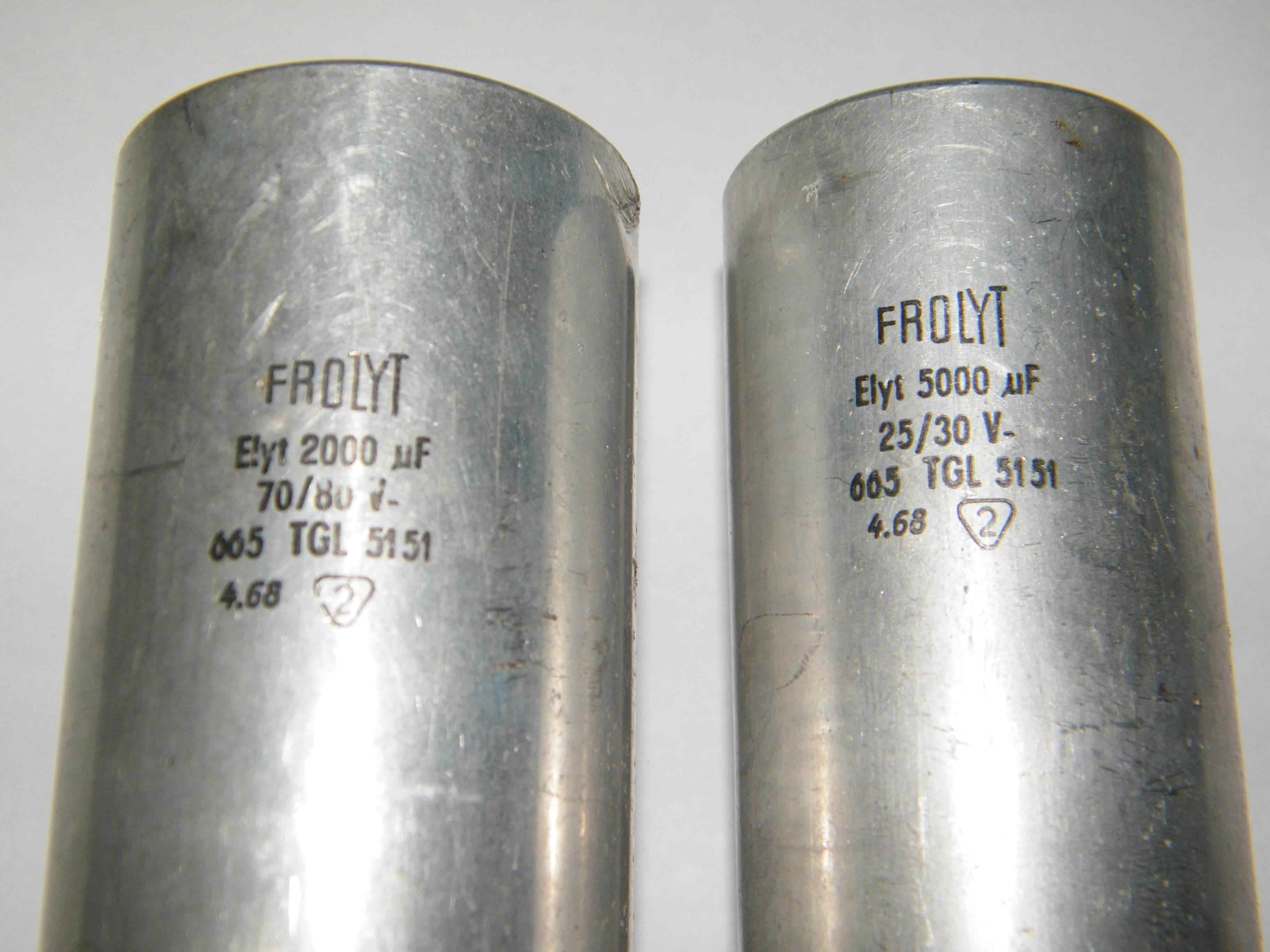
Main reservoir capacitors
Click image for a larger version
A data sheet for the main reservoir capacitors has been obtained from the original manufacturer Frolyt, but it unfortunately did not give any indication of values for leakage currents. Examination of the mechanically damaged capacitor showed no actual electrolyte leakage so the decision was taken to try the capacitors on a low voltage DC source and measure their currents, this showed that they were close to their original capacitance values with very low leakage currents. We then reformed the capacitors gradually bringing them up to their working voltages over a period of 12 hours. No temperature rise was found over this time, confirmed by their continuing low leakage values.
At this time we think these capacitors are suitable for use in spite of their age so they have been reinstalled in the power supply. The next step of the refurbishment will be to apply mains power to the unit through a Variac so that it can be gradually brought up to full working voltage whilst monitoring the power supply output levels. If this test is successfully we will then try powering our ETR224 with various sub-assemblies of the machine, checking each part for correct operation.
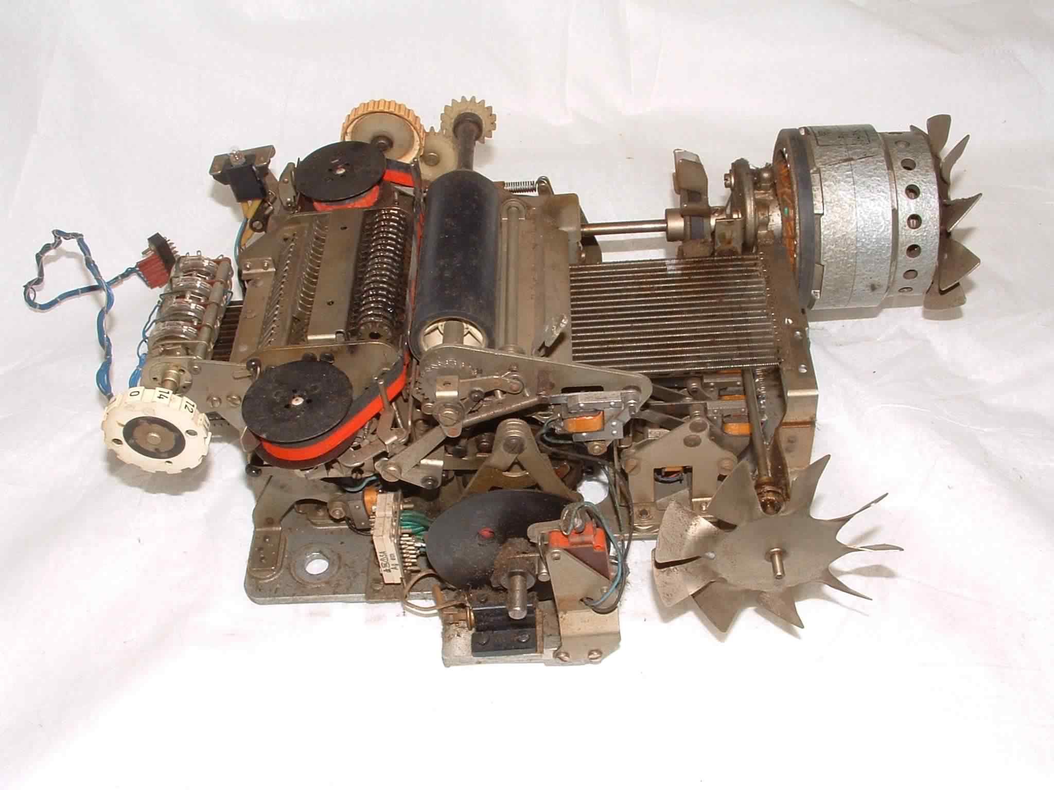
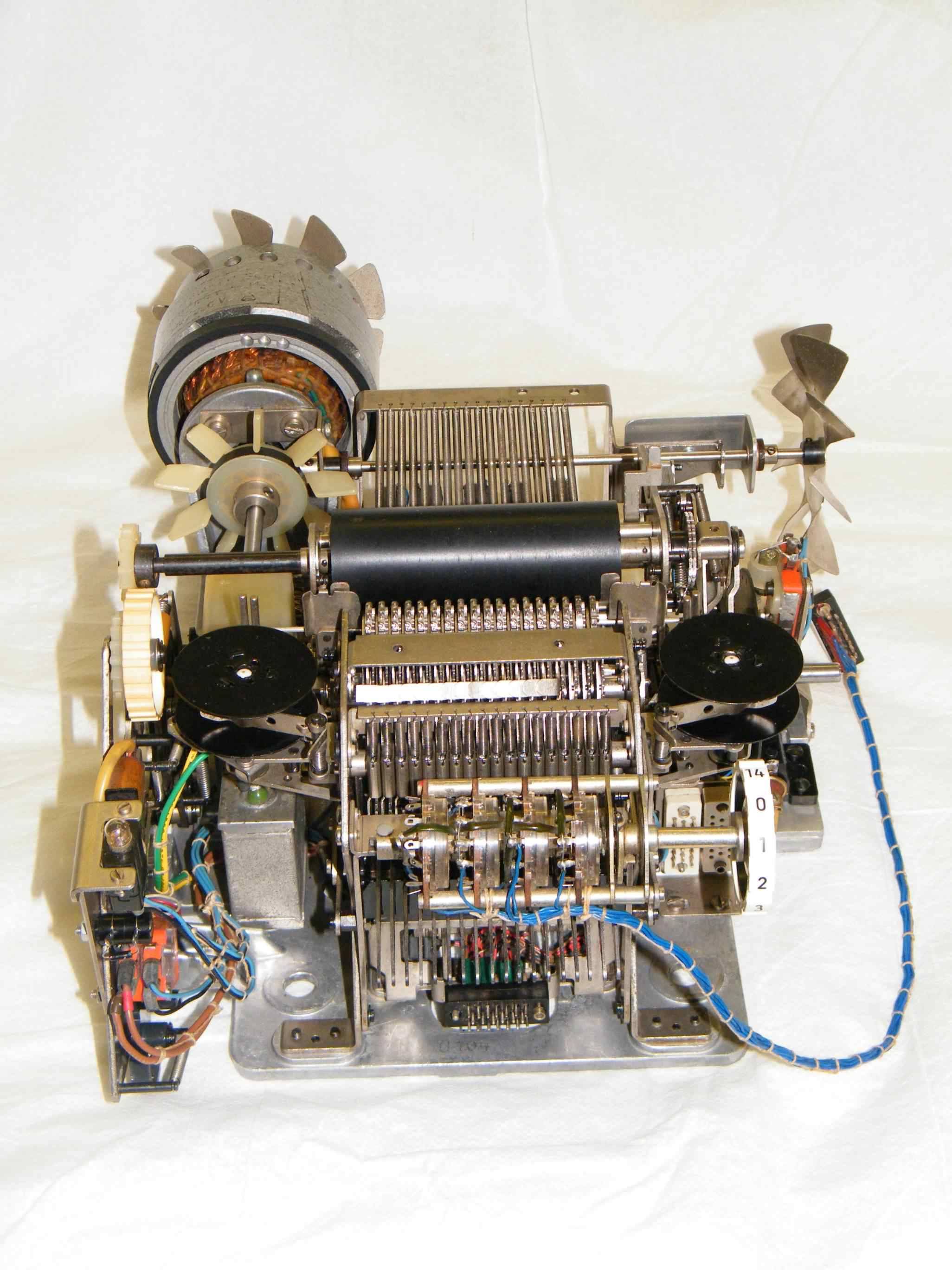
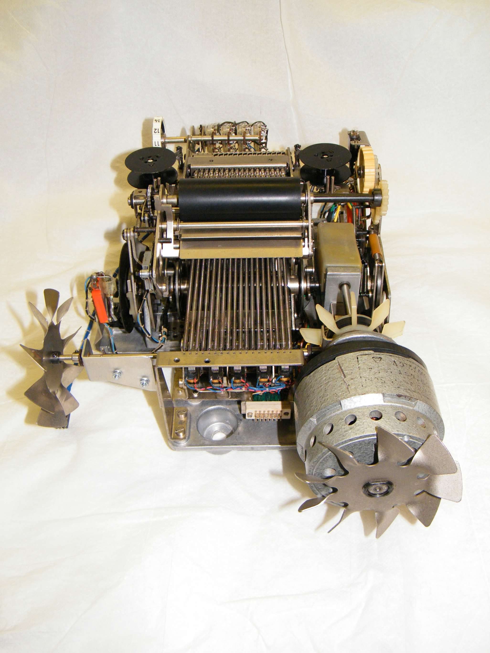
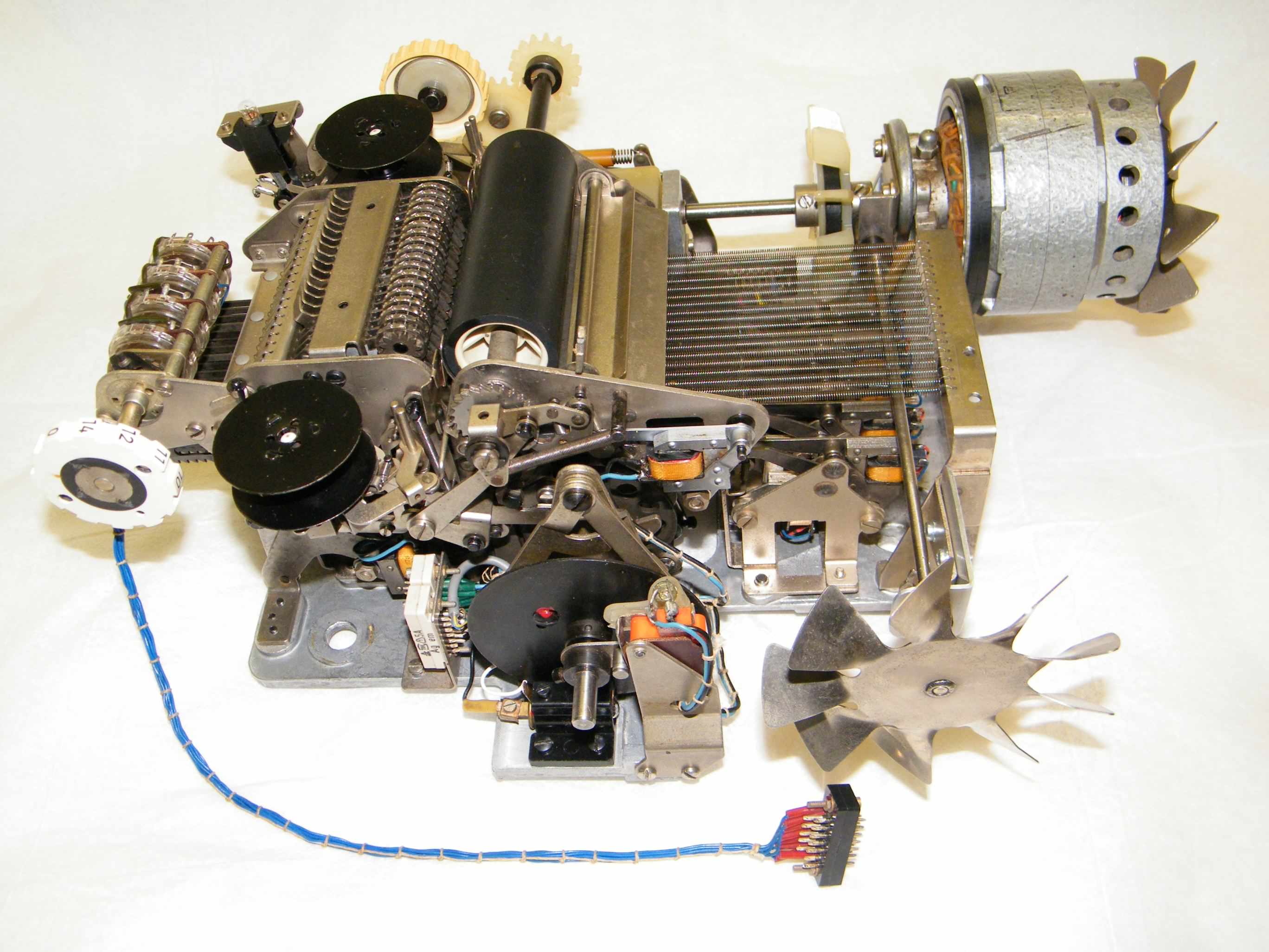
Printer mechanism - mechanical (S#D104) - circuit
 |
 |
 |
 |
And these after restoration –
 |
 |
 |
 |
| Click any image for a larger version | |||
From the markings on several parts of our printer mechanism and the way it is pinned together it would appear each printer is a custom build. The printer mechanism consists of, and can be conveniently be broken down into, several smaller mechanical sub-assemblies or modules consisting of –
Print wheel layshaft assembly
Click image for a larger version
- Left side plate, drive clutch, mains switch /indicator, manual paper advance gearing.
- Print roller, paper feed pinch roller, single / double line spacing mechanism.
- Front print wheel position selector assembly, eight selectors.
- Rear print wheel position selector assembly, ten selectors.
- Ink ribbon feed, reversal and colour selection assembly.
- Print wheels lay shaft assembly. (See picture right)
- 8:1 gearbox, main shaft and various drive cams assembly.
- Drive motor and coupling with a right angle friction drive to the electronics cage fan.
- Decimal point selection switch assembly.
Printer mechanism - operation
In the printer mechanism a print cycle takes one complete revolution of the main shaft, which as it is driven through an 8:1 worm and wheel gear train from the drive motor conveniently allows us to describe the operation of the printer in terms of drive motor revolutions, or eight stages.
| Stage | Operation |
| -3 to -1 | Slack time required to bring the drive clutch to full engagement. Following activation of the drive clutch solenoid it can take up to three revolutions of the motor to bring the drive to the correct position for printing. |
| 1 to 4 | During these four motor revolutions the eighteen individual print wheels are rotated via selector racks and intermediate gears on a common lay-shaft. As each print wheel rotates forward from its rest position, each digit to be printed is compared with a position count from an encoder disc on the print mechanism main shaft. An equality in the count and a required digit activates the respective print wheel solenoid, stopping the print wheel in the correct position. At the end of this stage each print wheel will be at rest or stopped in its correct position (0123456789,+-*/). |
| 5 | The eighteen print wheels with each wheel stopped in position, are then all rotated forward on another lay-shaft, a small pawl automatically locks each wheel in position which then contact the paper on the print roller through the ink ribbon. |
| 6 | The print wheels are returned on their lay–shaft back to their rest position in contact with the intermediate gears. |
| 6 to 7 | Advance the ink ribbon and print roller for the next print operation, also reset the ink ribbon back to its black setting if required. Also if required the print roller will advance two lines during this time if the paper advance solenoid has been tripped, otherwise the paper roll automatically advance one line only. |
| 7 to 8 | Spin the eighteen print wheels back to their rest position, this action automatically resets the print wheel stop solenoids. Miscellaneous other latches are also reset as is the drive clutch. This operation only takes two revolutions of the motor as opposed to the four revolutions it took to set up the print wheels, as there is no requirement to select digits for printing. A microswitch operated off another cam and pin on the main shaft encoder wheel, signals completion of the current print operation back to the control electronics. |
Other controls on the printer mechanism allow the user to manually advance the paper roll and to release the paper feed pinch roller so that the paper roll can be changed. Positive results are printed in black , and negative results are printed in red under control of a release solenoid that allows the ribbon to pop up presenting the red half of the ribbon, it is mechanically reset during period 6/7 of a print operation.
The motor is a two phase induction motor of an external rotor design, I.E. the squirrel cage rotor spins on the outside of the stator, this gives the motor a higher inertia value as the rotor also acts like a flywheel. This higher inertia would appear to be required for the ETR224 printer mechanism to get over the high initial torque of engaging the clutch and rotating the main shaft off its stopped position. The speed of the motor calculates to 1500rpm and actually measures at 1490rpm, so through the 8:1 worm drive this results in a single line print timing of 322mS. With the possible three revolution latency in the drive clutch, a one line print can take somewhere between 322mS and 442mS, giving a maximum print speed of three lines per second. A fan on the back of the rotor provides motor cooling, whilst a rudimentary Oldham coupling on the motor shaft attempts to cater for any motor misalignment. A rudimentary right angle friction drive from the back of the Oldham coupling powers a fan in the electronics card cage, circulating air from the inside of the unit through the printed circuit cards.
Printer mechanism - Digit position photo–sensor amplifier –
Damage to the wiring loom of the printer mechanism's digit position photo sensor amplifier had rendered the amplifier non operational, possibly from a previous repair to the cable screen or faulty production, either way the screen wiring had too much solder in the joint and the screen parted company at the point where the screen joins the cable.
We replaced the complete wiring loom, however lacking a single core screened cable replacement, the amplifiers screened cable is wired with a two cored variant in a similar manner to the original but with the two cores in parallel, the other two wires in the assembly were replaced in the same size but in differing colours rather than cause any confusion with the original loom's two Green wires. For the photo amplifier circuit see the printer mechanism circuit above.
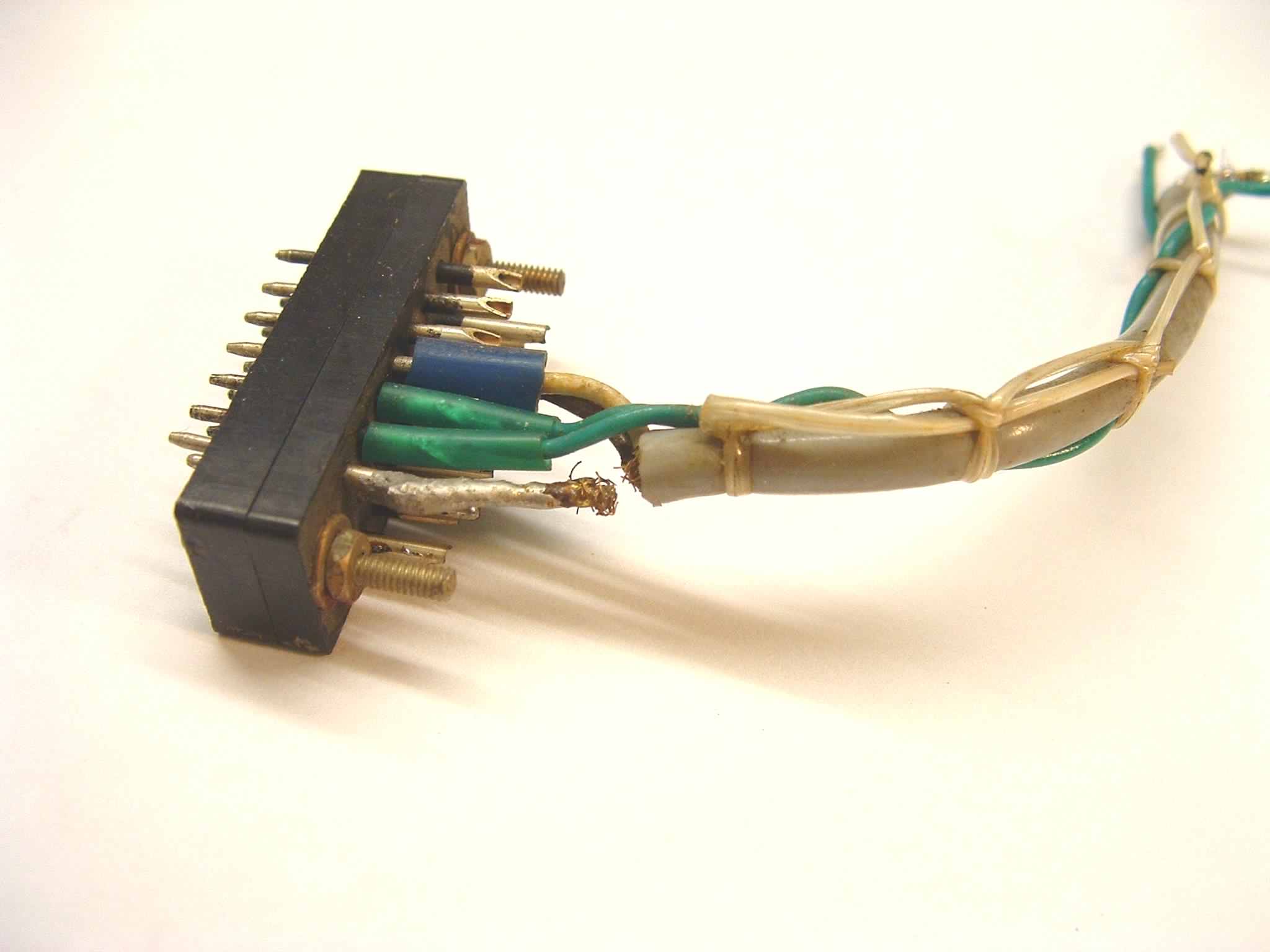 Broken sensor cable |
 New photo sensor wiring |
| Click any image for a larger version | |
Printer mechanism - Solenoid driver board and sub assembly – circuit
The twenty small solenoids on the ETR224 printer mechanism are all powered by drivers formed from a basic monostable circuit with a driver stage. Twenty drivers are split into two boards with ten drivers on each board, with each board plugged into a sub-chassis with integral wiring harness and connectors for the harnesses from the printer mechanism and digit detection circuits. A small adjustable bracket mounted on the back of the printer mechanism clamps the boards in place preventing them from working loose in their connectors.
When the solenoids are tripped they latch escapements in the printer mechanism which perform the following tasks -
- Sixteen solenoids which stop the position of the sixteen left-most print wheels in the printer mechanism. Each wheel prints 0–9 and comma.
- Two solenoids stop the position of the two right–most print wheels of the printer mechanism which show the current arithmetical operation.
- One solenoid releasing a drive clutch which engages the continuously spinning motor to the main drive shaft of the printer through an 8:1 worm and wheel reduction gear train.
- Lastly one solenoid engaging a double space paper feed mechanism.
All the solenoids are automatically reset or disengage during completion of the current printing operation.
Initially it might seem a little strange to have sixteen print wheels for a machine only capable of fifteen digits, however the extra wheel ensures that the current position of the decimal point "comma" can be inserted into a printed result and still show the full fifteen digits.
A 21st solenoid on the printer mechanism used to start the printer to output a line is not driven from the driver boards themselves, but is directly connected to a driver transistor on the under keyboard printed circuit board, which in turn is driven from a two input gate on board 6. Twin 3K3 resistors and 50uF capacitors ensure the trip to the Start solenoid is time limited.
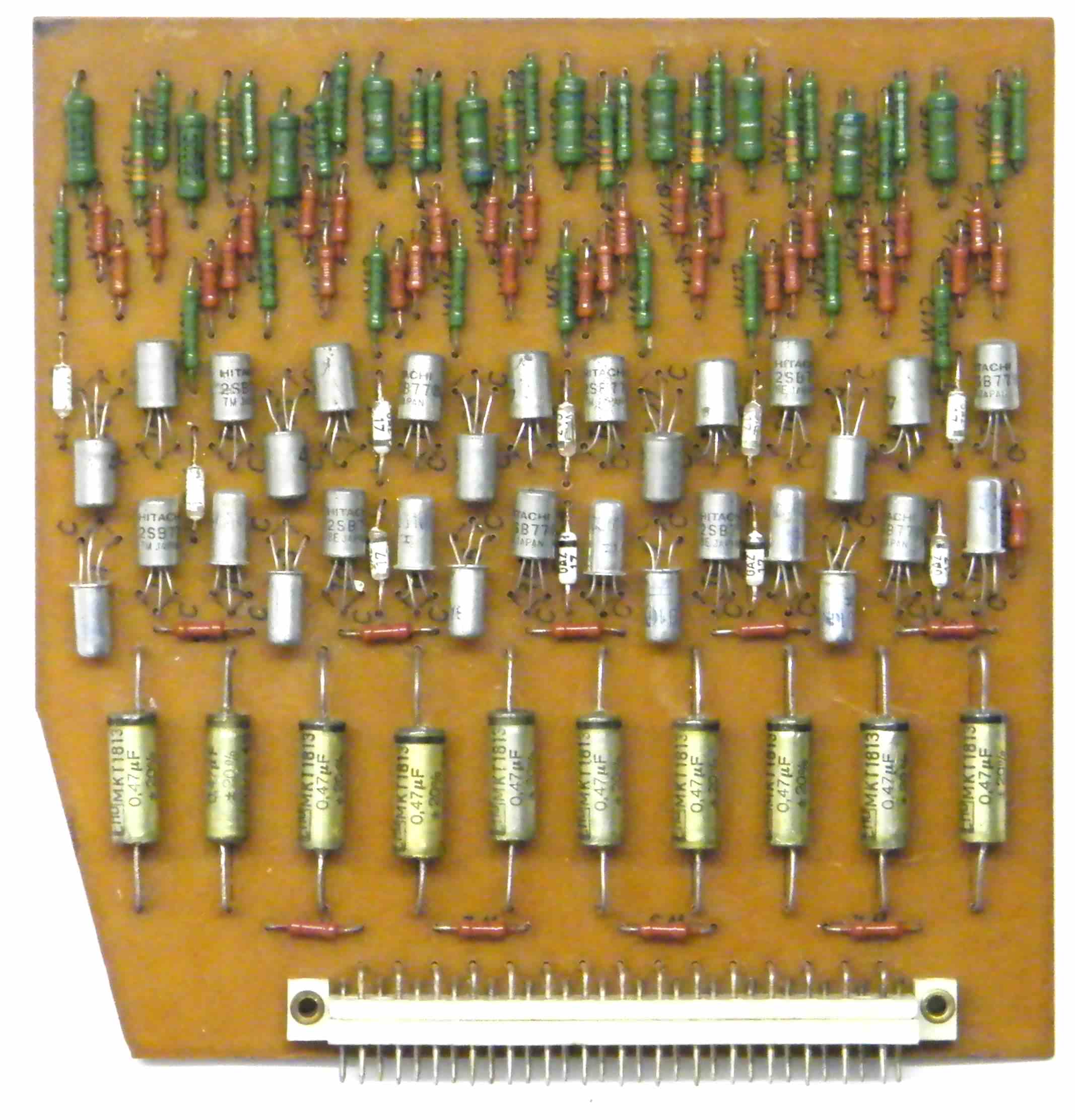 Solenoid driver board |
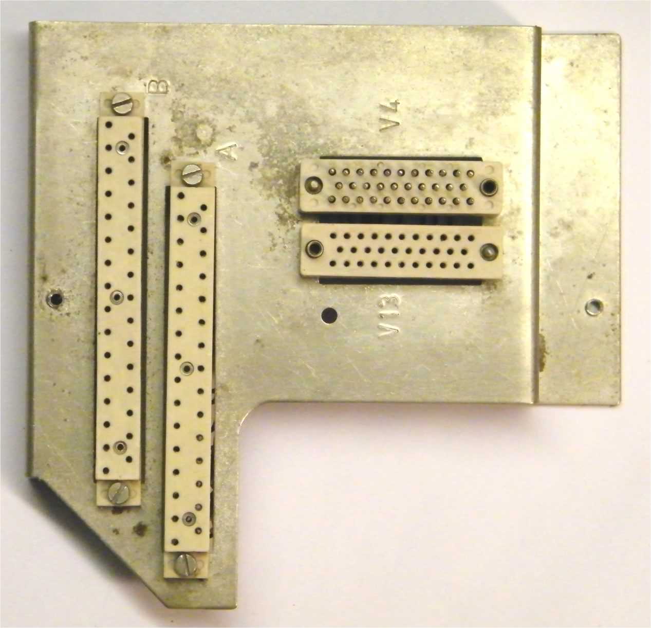 Sub assembly panel |
 Sub assembly panel |
 Complete driver assembly |
| Click any image for a larger version | |||
- Febana as company is still in operation in Sömmerda and still producing switches. Febana's website [back] [top]
Site design ©2007– soemtron.org - privacy -